-
-
The first step in getting your design ready is to create a new project.
-
Click the “Create a new file” link on the left side bar.
-
-
-
Change the width and height of your job. This is generally the size of the stock you’ll be cutting from.
-
Set your material thickness and your Z-Zero location.
-
If you choose the TOP radio button, you will zero the machine to the top surface of your material.
-
This method is best for engraving, carving, or machining features which don't go all the way through the stock.
-
If you choose the BOTTOM radio button, you will zero the machine to the empty bed next to your material.
-
This is the prefered method for through-cutting jobs as it prevents (or reduces) scar marks on the spoilboard.
-
-
-
Set your XY Datum (XY zero) location.
-
You can choose any of the 5 positions indicated.
-
This point will be the point on the parent stock that you will zero the machine’s X-Y axis to during machine setup.
-
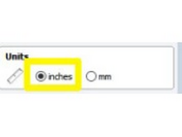
Choose “Inches” for your units.
-
-
-
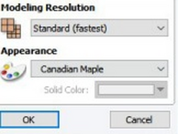
The modeling resolution and appearance settings can be adjusted as you see fit. Setting the modeling resolution to “Standard (fastest)” generally provides good quality preview.
-
Appearance only affects the preview appearance of the job. It has no effect on feeds or speeds.
-
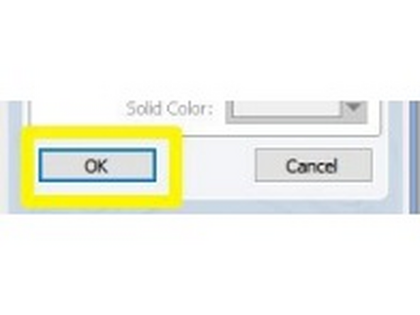
Click OK to create your job.
-
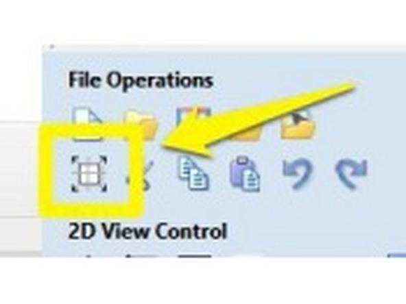
You can access these initial settings again at any time by clicking on the “Job Settings” icon under “File Operations”
-
-
-
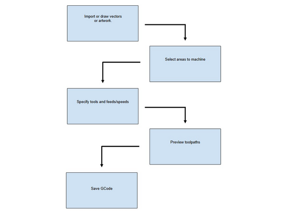
Import or draw vectors or artwork.
-
Select areas to machine
-
Specify tools and feeds/speeds
-
Preview toolpaths
-
Save GCode
-
-
-
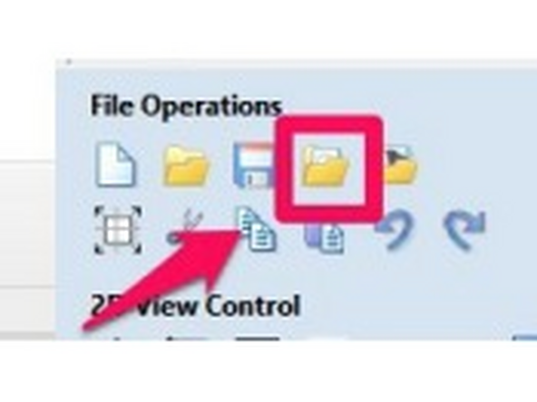
Vectric can import many vector graphic formats including SVG and DXF (probably the most commonly used.
-
Under “File Operations” click the “Import vectors from file” button
-
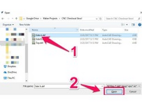
Locate the file you’d like to import and click “Open”
-
Repeat the above steps for all the artwork that needs to be imported.
-
Imported artwork is ungrouped, it can be helpful to arranging things into a job to group objects. Select the objects, RIGHT click, and select “Group Objects” from the menu.
-
-
-
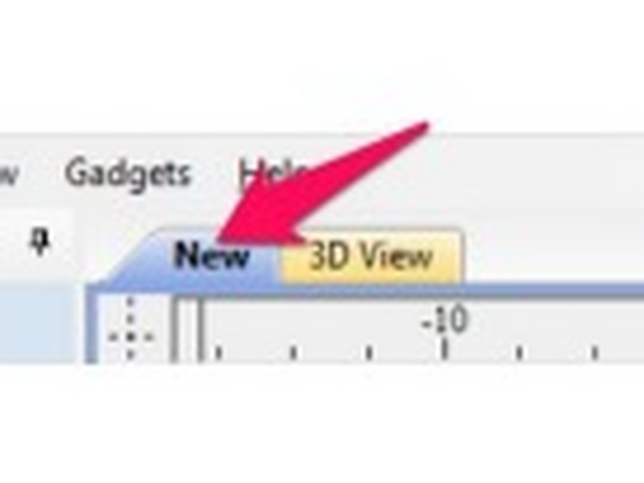
Make sure you are in the drawing view tab (NOT the 3D View tab). This tab will have the name of your file, or “New” if the file hasn’t been saved.
-
Click the drawing tab if it’s not already selected.
-
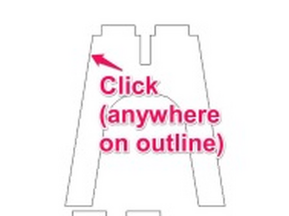
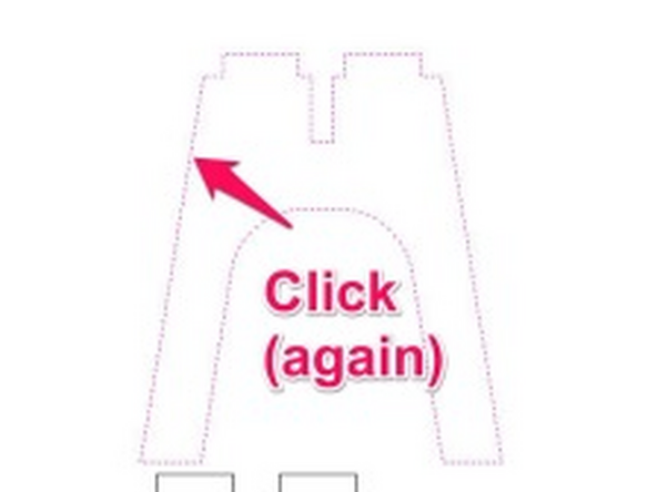
Click anywhere on the outline of a path to select it.
-
For ungrouped multiple objects, you can use a selection window to select the objects together by clicking and dragging, or hold shift and click each object individually.
-
-
-
With the first click, the path will be highlighted. Click AGAIN to active the move tools.
-
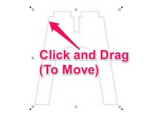
The move/resize handles show appear on the object or objects you are moving. Click and drag anywhere on the selected paths (your cursor will change to a “Move” icon) to move the object on your work piece.
-
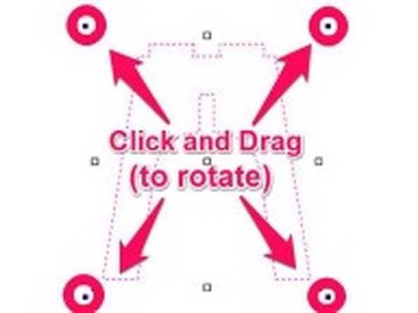
To rotate your path, click and drag the filled squares in the corners of your path. (rotate handles). Your cursor should change to a “Rotate” icon.
-
Holding shift while rotating will lock the rotation to incremental degrees (rather than allowing fully free rotation)
-
-
-
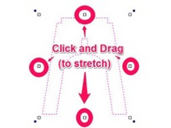
To STRETCH your path, click and drag one of the four handles on the SIDES of your path.
-
Proportionality ISN'T preserved when stretching!
-
-
-
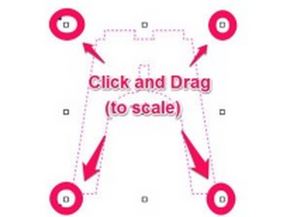
To SCALE your path, click and drag one of the four unfilled squares in the CORNERS of your path.
-
Proportionality IS preserved when scaling.
-
-
-
Adding text objects in VCarve is a useful tool for creating v-carving tool paths.
-
Make sure you are in the drawing view tab (NOT the 3D View tab). This tab will have the name of your file, or “New” if the file hasn’t been saved.
-
Click the drawing tab if it’s not already selected.
-
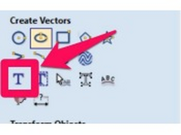
Click the Text tool icon in the drawing panel, under “Create Vectors”
-
-
-
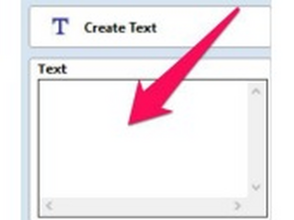
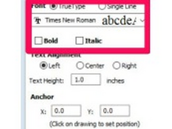
Enter your text into the dialog box.
-
Select your font, and your Font Options (bold, italic, etc).
-
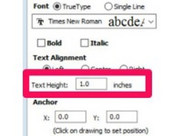
If you want your text to be a certain height, enter the text height in inches.
-
-
-
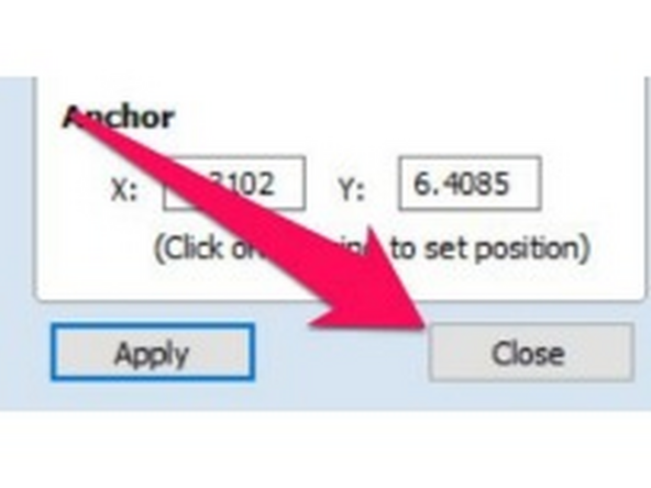
Click anywhere in your drawing to insert the text at that position.
-
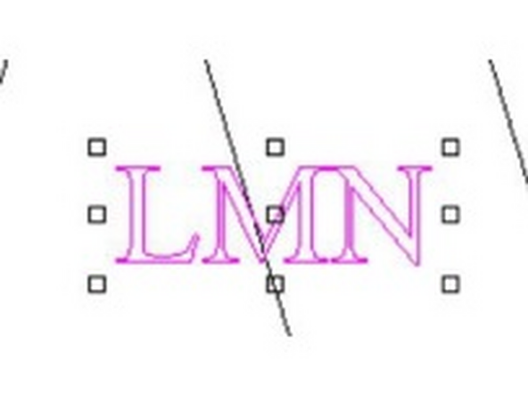
Click “Close” to close the text entry dialog.
-
You can now use the move, scale and rotate tools to move your text anywhere on your drawing.
-
-
-
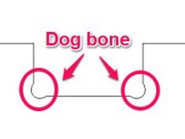
Dog bone fillets allow two mating pieces of material to come together completely, accounting for the inability of the router to make a square corner in a part.
-
Identify the places in your artwork where you will need dogbone fillets.
-
While you could create dog-bone fillets in the tool you used to create your art work (Illustrator, Fusion 360, etc), Vectric makes it pretty painless to add them.
-
-
-
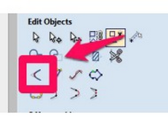
Click the “Fillet” tool.
-
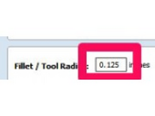
Enter a value equal to or larger than the RADIUS of your tool.
-
For example, a 0.250" (1/4in) end mill would require a minimum radius of 0.125", but a larger value like 0.150" would give better cut quality and tool life.
-
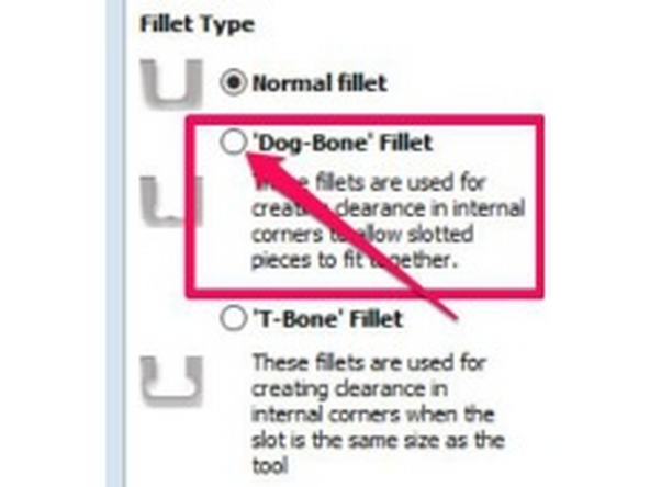
Click the radio button next to “Dog-Bone Fillet”
-
The "Dog-Bone" radio button produces fillets with the minimum amount of material removed to make clearance.
-
The "T-Bone" radio button produces fillets which are tangent to one side of the joint. This is necessary when there is not enough material on both sides of the corner, such as slots with the same diameter as the tool.
-
-
-
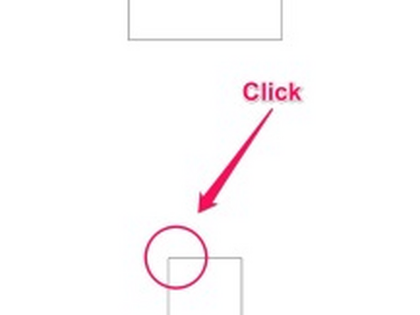
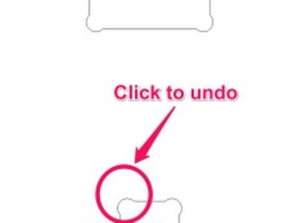
Click the corner you’d like to add a fillet to. The corner will redraw with the appropriate fillet.
-
The "T-bone" fillet requires you to click on one of the lines near the corner to specify which way it should go.
-
To UNDO a fillet, you can click the corner again, and the fillet will be removed.
-
-
-
Profile toolpaths generate code that drives the tools to follow the inside OR outside of a path, often to cut a part out of the parent stock.
-
Make sure you are in the drawing view tab (NOT the 3D View tab). This tab will have the name of your file, or “New” if the file hasn’t been saved.
-
Click the drawing tab if it’s not already selected.
-
-
-
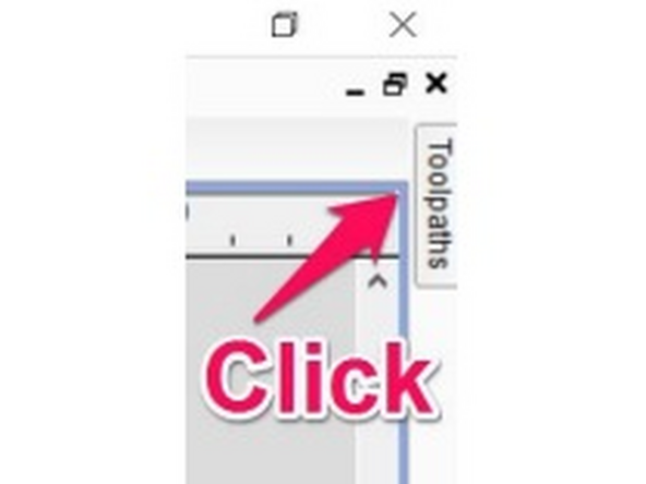
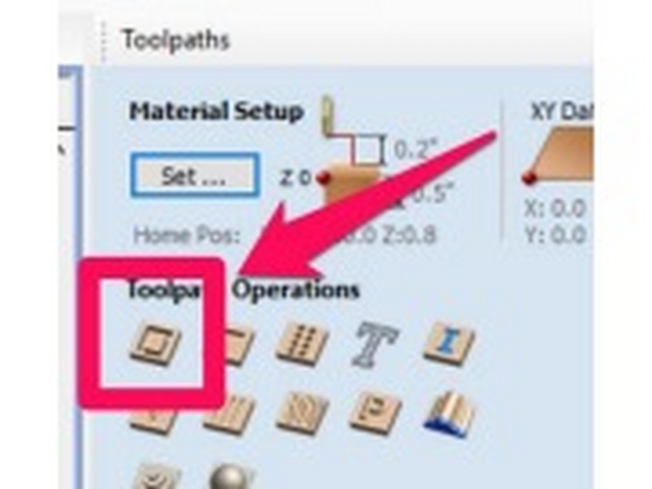
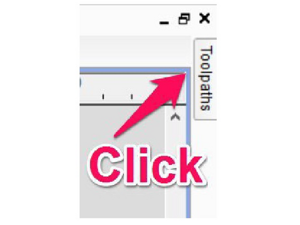
Click the “TOOL PATHS” on the right hand side of the screen.
-
Click the “Pin” to keep the toolpath flyout open.
-
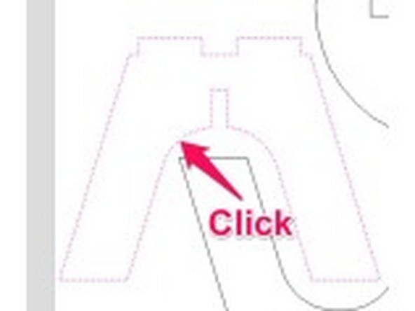
Click the shape you want to create a profile path for to select it.
-
In the Toolpaths flyout, click the Profile Toolpath Button
-
-
-
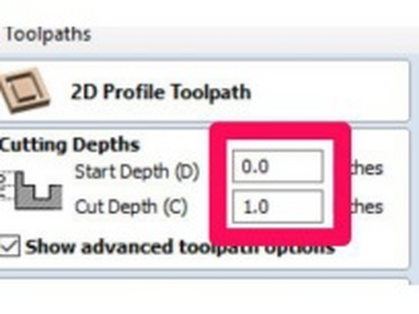
Enter the “Start Depth” and the “Cut Depth” for your profile.
-
Start depth is USUALLY 0.0. If your profile path will cut the part out fully, set the cut depth equal to your material thickness.
-
Setting the cut depth larger than your material thickness could cause you to cut into the spoilboard.
-
-
-
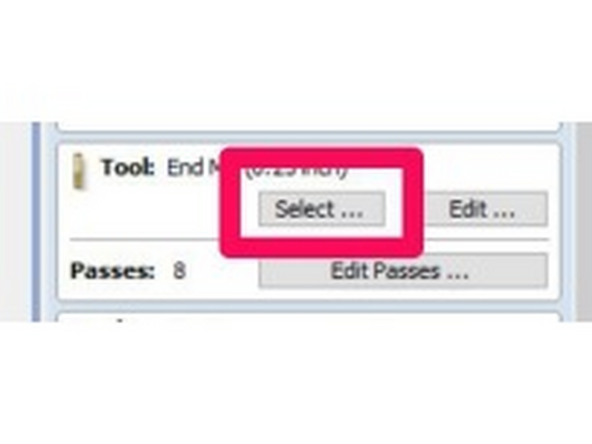
Click “Select...” in the tool section.
-
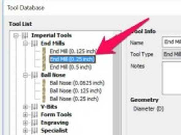
Click to select the appropriate tool.
-
If you don’t find an appropriate tool for your toolpath, you can click “New...” to create a new tool.
-
Click OK to close the tool selection dialog box.
-
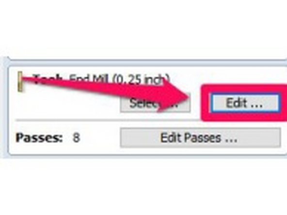
If you make changes to feeds and speeds in the tool selection dialog box, the changes will be saved as defaults for all users. Select a tool, and then click “Edit” to make sure your changes only apply to your toolpaths.
-
-
-
Click “Edit” to change the Feeds and Speeds for your tool.
-
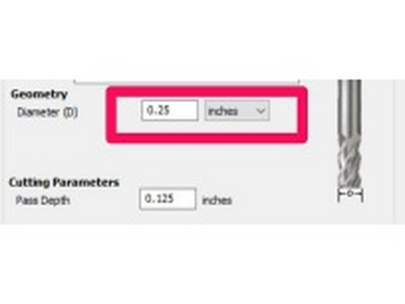
Check that the Diameter of your tool is correct and adjust as needed.
-
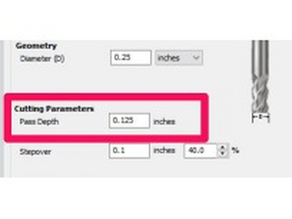
Check that the “Pass Depth” is appropriate for your cutter and your material.
-
For wood, generally a good rule of thumb is to set your pass depth to no more than the cutter diameter
-
-
-
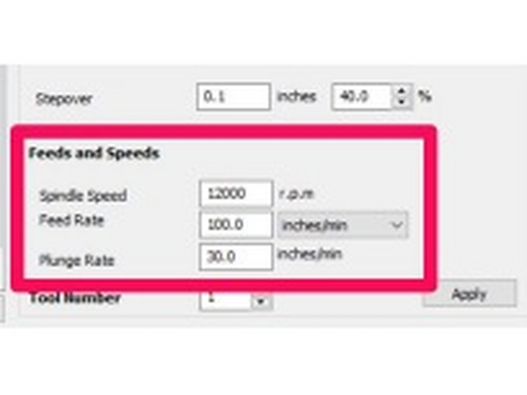
Set your feeds and speeds.
-
Feeds and speeds should be calculated or adjusted based on cutter geometry / size, number of flutes. Please reference the cutter manufacturers' resources if available.
-
A useful number is the "Chip Load" which is calculated from the parameters above. Most router bits are designed for a specific chip load.
-
If you are just using 1/4in 2 flute bits, a good starting point is 120 inches per minute (IPM) and 18000RPM
-
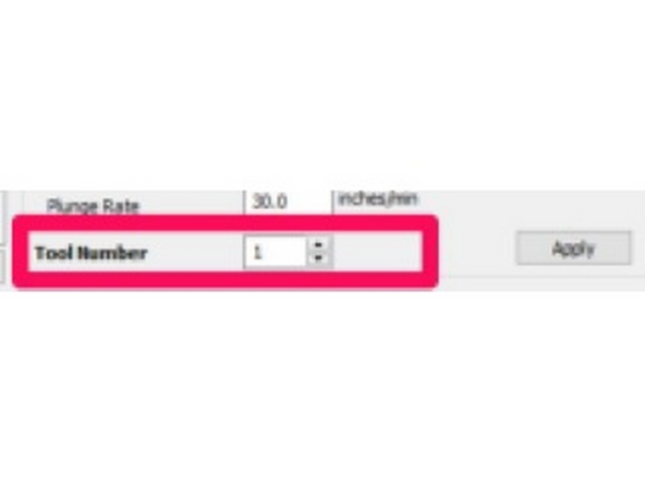
Specify the Tool Number based on the position it is loaded on the machine.
-
It is imperative that the tool number specified here is correct and that the proper tool is loaded in that holder. You can cause serious damage to the machine if this is not double and triple checked.
-
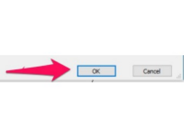
Click OK to close the edit tool dialog box.
-
-
-
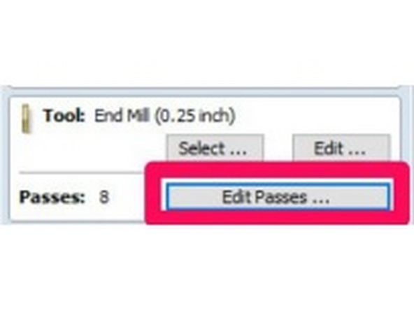
The number of passes should be automatically set based on your cut depth and the pass depth set in the tool, but you can click “Edit Passes” to make any changes needed to the number or depth of passes.
-
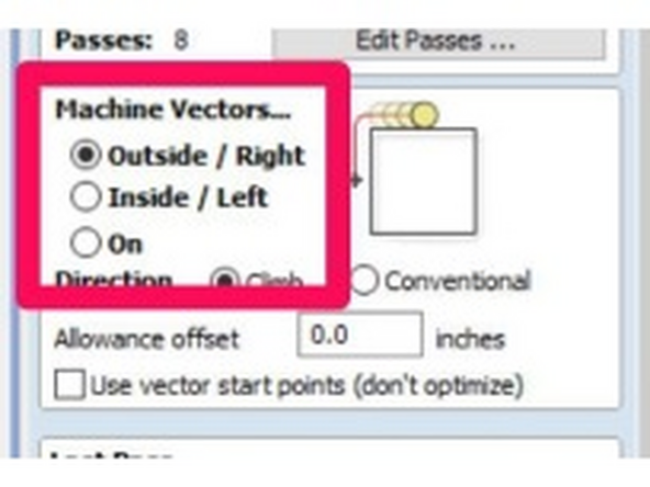
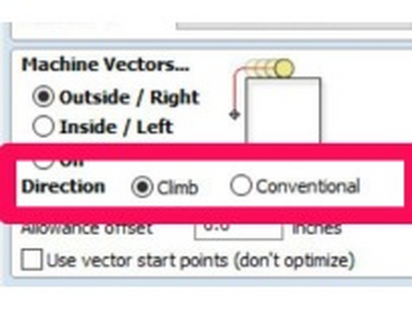
Under “Machine Vectors” choose the appropriate radio button to place the tool on the inside or outside of your path.
-
Choose the machining direction.
-
For most tool paths, you should choose the “Climb” direction. "Conventional" can be better in some cases for finishing passes.
-
-
-
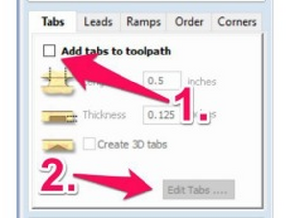
To add tabs to your toolpath, check the “Add Tabs” box and click “Edit Tabs”
-
Tabs are not always required depending on how you are holding your workpiece to the machine. If they are not required for your job, you can skip this section.
-
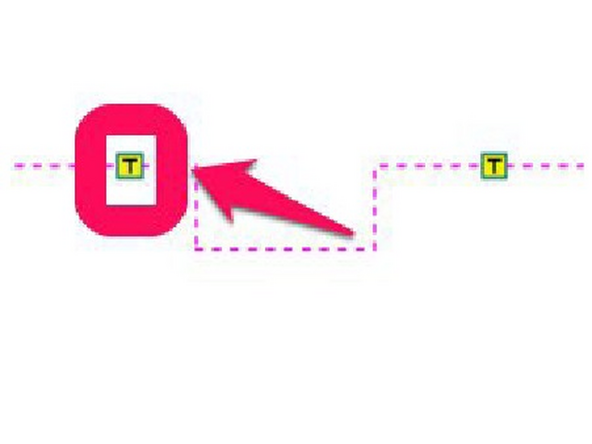
You can click anywhere on your path to add a tab at that location.
-
To delete a tab, hover over the “T” on your toolpath (Your cursor should change to an “X” icon) and click.
-
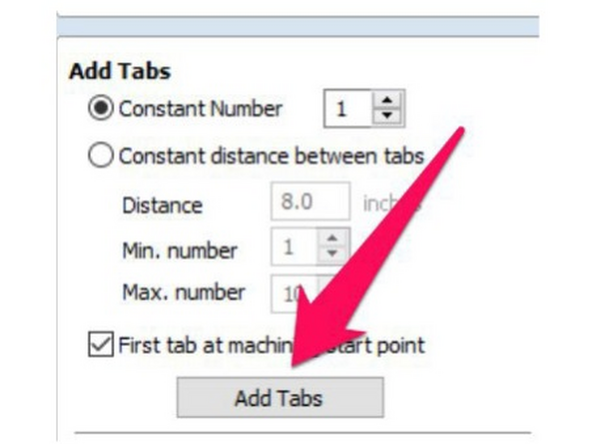
Alternatively, you can have VCarve automatically add your tabs at specified intervals. Adjust the settings and click add tabs.
-
-
-
Set the Length and height of your tabs.
-
A good rule of thumb is to set the Thickness to 1/4 - 1/3 of your material thickness, and the length to 1/2 - 3/4 of your material thickness.
-
Make sure your material thickness is set correctly, or you could cut your tabs off during machining.
-
If you have multiple pieces close together, your tabs can be cut away as the profile of the piece next to it is cut. It is a good idea to leave enough space to have "islands" of stock left in between parts, or to put a corresponding tab on the other piece.
-
-
-
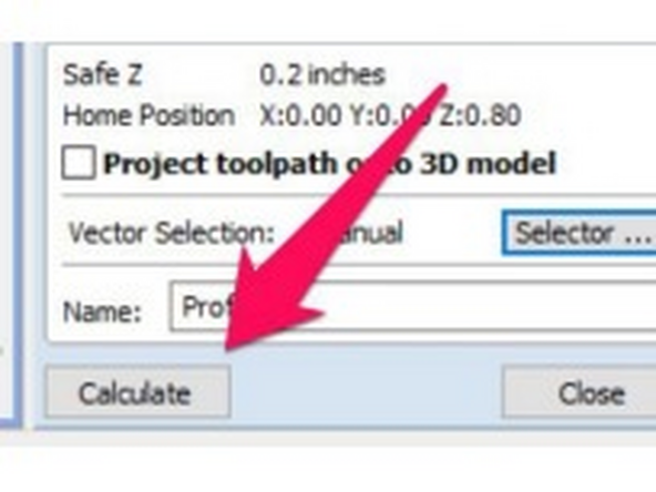
Click “Calculate” to generate your toolpath.
-
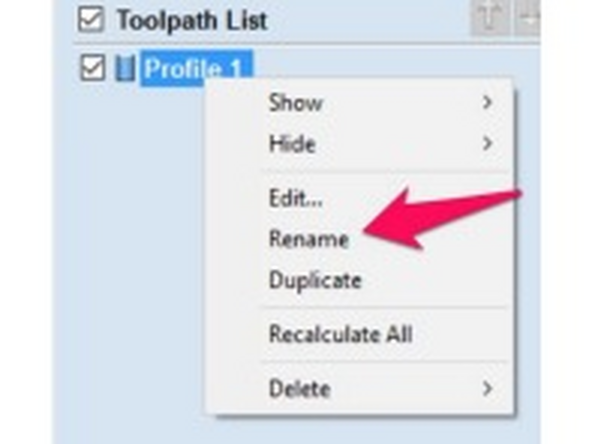
Your tool path should now show in the list of toolpaths. Click “Rename” to change the name of the toolpath.
-
Renaming tool paths helps keeps your project organized, but isn’t 100% required.
-
Switch back to the drawing tab. (VCarve probably switched to the 3d View tab when you clicked calculate)..
-
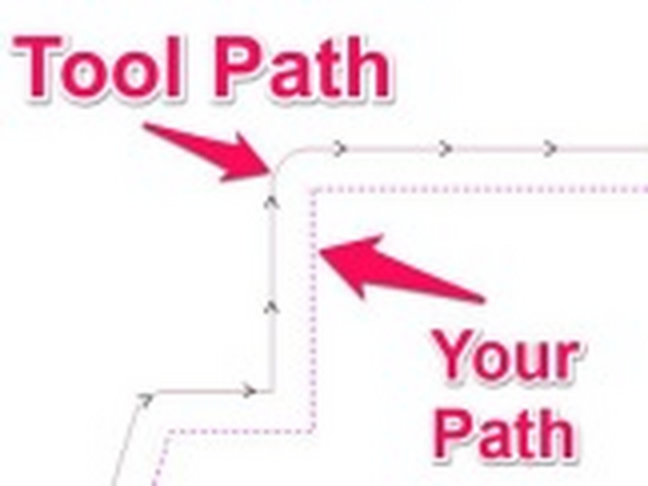
The line with arrow along it indicates the tool path that was generated. Double check that the path is on the correct side of the line. Right click on the Toolpath in the Toolpath list and select edit to change the Vector Direction if it’s incorrect.
-
-
-
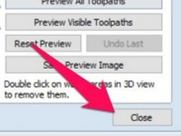
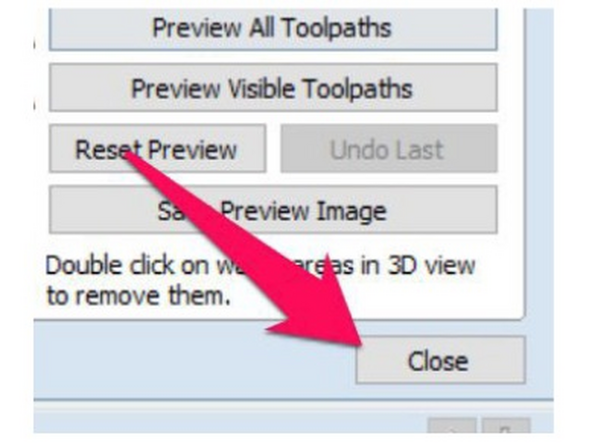
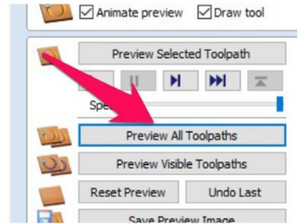
You can click “Preview all Toolpaths” to view the result of your tools paths. (You may have to switch back to the 3d View)
-
Click close when done to close the preview toolpaths dialog.
-
The dialog for adding additional toolpaths is under the preview dialog, so you’ll need to click close to add more tool paths.
-
-
-
V-Carve tool paths are usually used to engrave text or other patterns into your work..
-
Click the drawing tab if it’s not already selected.
-
Click the “TOOL PATHS” on the right hand side of the screen.
-
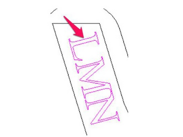
Click the toolpath you want to create a v-carve path for to select it.
-
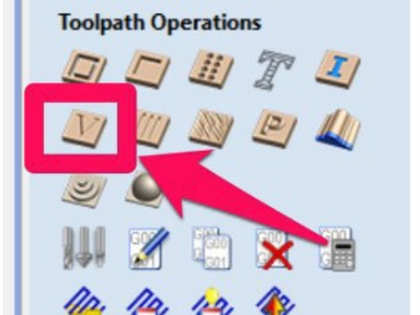
In the Toolpaths flyout, click the V-Carve Toolpath Button.
-
-
-
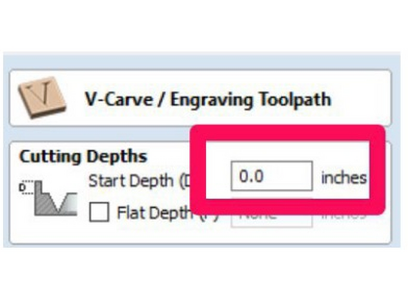
Enter the “Start Depth” for your carving.
-
Start depth is USUALLY 0.0. If you have already pocketed an area or done another operation, adjust your start depth accordingly.
-
Flat Depth is an advanced option that lets you create a flat area in the center of the profile, if there is enough room to create one.
-
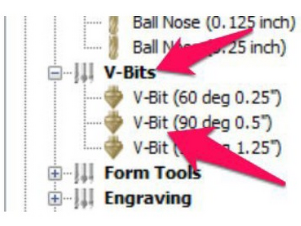
Click “Select...” in the tool section.
-
Click to select the appropriate tool, expanding the V-Bits section if need be.
-
If you don’t find an appropriate tool for your toolpath, you can click “New...” to create a new tool.
-
Click “OK” to select the tool.
-
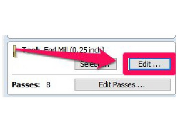
If you change feeds and speeds in the tool selection dialog box, your changes will be saved as defaults for the tool (for all users). Close the tool selection dialog box and click “Edit” to edit the feeds and speeds for only your toolpath.
-
-
-
Click “Edit” to change the Feeds and Speeds for your tool.
-
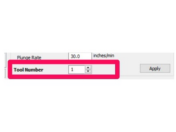
Check that the tool number if correct. If you only have one tool in your job, you’ll be fine with any number. If you are using multiple tools, just make sure that each tool has a different tool number populated.
-
It is imperative that the tool number specified here is correct and that the proper tool is loaded in that holder. You can cause serious damage to the machine if this is not double and triple checked.
-
Click OK to close the edit tool dialog box.
-
Click “Calculate” to generate your toolpath.
-
-
-
Your tool path should now show in the list of toolpaths.
-
You can now preview this toolpath as before. See Step 27 for more detail.
-
-
-
Generating G-Code is the step that creates a file that can be used by the CNC machine.
-
Click the “TOOL PATHS” on the right hand side of the screen if the toolpaths flyout is not already open.
-
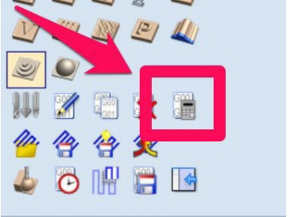
Before saving your GCode, you should recalculate all toolpaths. This ensures that any changes you have made are included in the saved tool paths.
-
Click the Recalculate All Toolpaths button in the Toolpaths flyout.
-
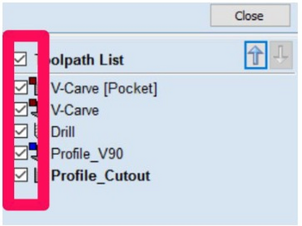
Make sure that all the tool paths you would like to include in this GCode file are CHECKED
-
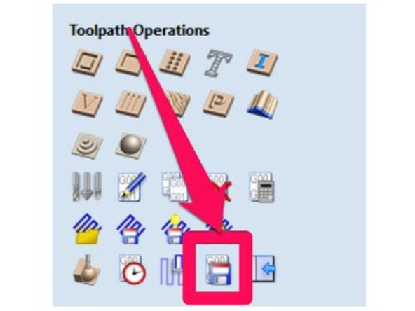
In the Toolpaths flyout, click the Save Toolpath button.
-
-
-
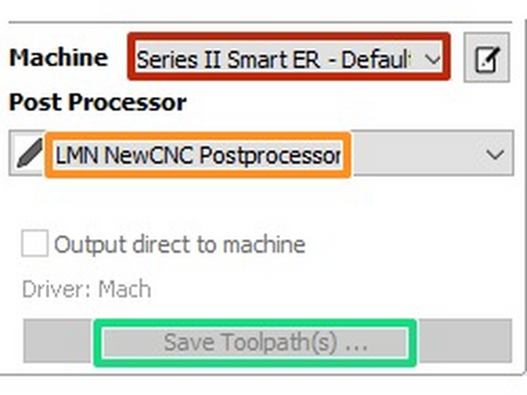
Now is a good time to double check the tool numbers listed in the save toolpaths window.
-
Change the machine dropdown to "Series II Smart ER - Default for regular jobs. Use "Series II Smart ER - Rotary" for rotary axis programming only.
-
Change the post processor to "LMN NewCNC Postprocessor"
-
Click “Save Toolpath(s)”
-
Choose an appropriate name and location to save your GCode, and click the Save Button.
-