
Difficulty
Moderate
Steps
14
Time Required
01:00:00

User-Contributed Guide
This guide is not managed by the site's staff.
Quiz
0
Introduction
Using the Hobart Handler® 140 MIG Welder
-
-
Apparel – all skin should be covered by leather of non-synthetic fabric – synthetics can melt and cause burns. Exposed skin will get sunburned from electric arc flash.
-
Leather gloves should be worn to protect hands – avoid handling hot metal with gloves – use pliers instead
-
Helmet- Mig welding needs at least a shade 11 lens welding helmet. (Higher is darker)
-
Don’t weld galvanized metal, or any metal with a plating (chrome, galvanized, cad-plated, etc.) These can release poisonous gases – especially galvanized. If you need to weld these, grind off surface anywhere near the weld.
-
Don’t weld anything that has been in contact with flammable liquids (IE don’t weld gas tanks or oil pans)
-
-
-
Machine Electrical power connection 110 VAC
-
Ground clamp connected to the metal welding table or the work piece
-
Torch/Gun/Electrode where all the sparks and welding takes place.
-
-
-
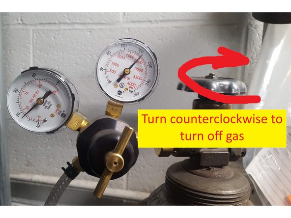
Open Argon/ CO2 75/25 tank main valve all the way. check that shield gas is set to 20 cfh (cubic feet per hour) on gauge. If you are getting bad welds, it is likely that you forgot to open the shielding gas.
-
-
-
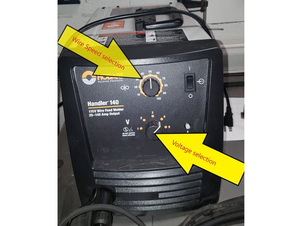
To use the chart, determine the thickness of your metal, and the current wire thickness (it will generally be .030). We use Argon CO2 gas, so locate the line on the chart for Argon CO2 and .030 wire and go across to your metal thickness. Dial in the correct voltage and wire feed rate.
-
A copy of the chart is posted in the welding area for convenience. The chart is also located on the inside cover door panel left side where wire spool is located.
-
As an example the steel is determined 10 gauge (.135 inch) the wire speed would be 4 and voltage 50.
-
If your weld is high, or flat you may need to adjust voltage and wire speed. See pages at the back of this SOP for guidance.
-
-
-
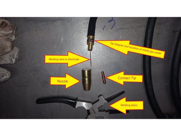
While welding, the nozzle may get a buildup. This will block the flow of shielding gas. Nozzle gel can be used to reduce this problem. From time to time you should remove the nozzle and use the welding pliers to remove buildup.
-
The mig tip can become clogged. If this happens, first see if running the ruff edge of the pliers or a wire over the mig tip will release the wire. If not, you may need to unscrew the mig tip and replace it with a new one.
-
Contact Tip only needs be snug. Do not over tighten as will damage the tip cause multiple issues including wire not feeding properly
-
Nozzle goes on with a twist. You do not require an tools to attach. The nozzle keeps the shield gases concentrated in the weld area.
-
-
-
Retrieve demonstration material
-
go over setup and shutdown, including cleanup and when the grinder is needed during cleanup.
-
Material must be clean (no galvanized or painted surfaces where welding/remove dirt and oil before welding). Cleaning material with grinder may be necessary to remove mill scale, rust, or and other material that will inhibit proper welding.
-
Demonstrate spot welding minimum of 3 beads
-
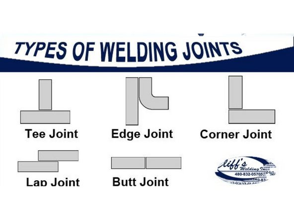
Demonstrate lap weld Also considered a fillet type, the weld can be made on one or both sides. A Lap Joint is formed when 2 pieces are placed in an over lapping pattern on top of each other.
-
Demonstrate Butt welds are welds where two pieces of metal to be joined are in the same plane. Talk about chaphering.
-
Demonstrate Tee weld/ Tee welding joints are formed when two members intersect at a 90° angle which makes the edges come together in the center of a plate or component. Tee Joints are considered a type of fillet weld, and can also be made when a pipe or tube is welded onto a base plate.
-
-
-
Turn off machine
-
Turn off Argon/CO2 cylinder.
-
Coil stinger(welding tip) and ground cable clean area and put tools away
-
if spatter or welds stick to table, remove with angle grinder.
-
Put away helmets, lens up to prevent scratching
-
-
-
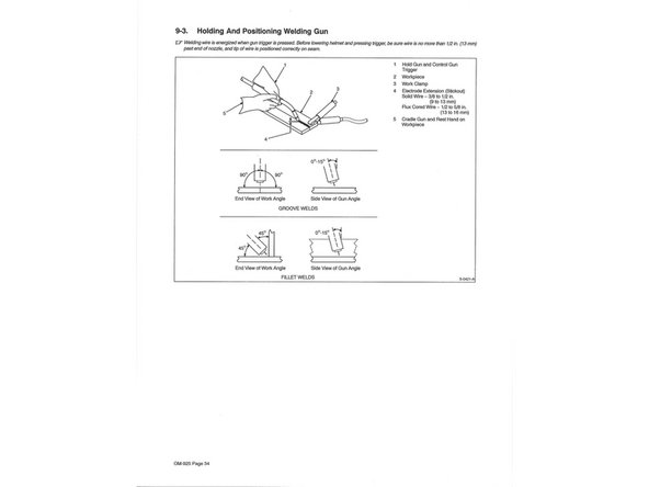
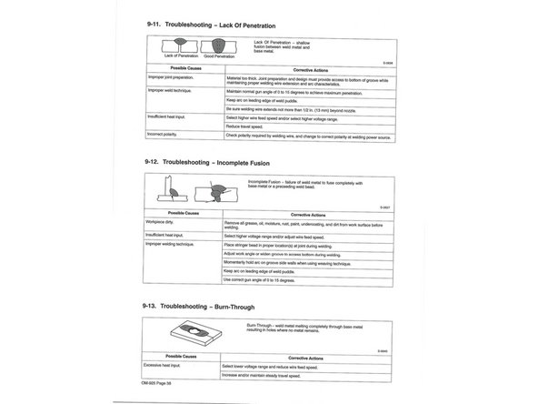
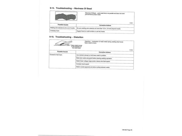
Welding wire is energized when gun trigger is pressed. Before lowering helmet and pressing trigger, be sure wire is no more than 1/2 in. (13 mm) past end of nozzle, and tip of wire is positioned correctly on seam.
-
-
-
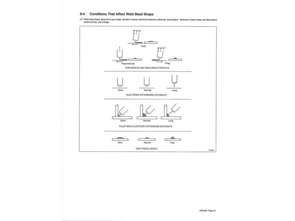
Weld bead shape depends on gun angle, direction of travel, electrode extension (stickout), travel speed, thickness of base metal, wire feed speed (weld current), and voltage.
-
-
-
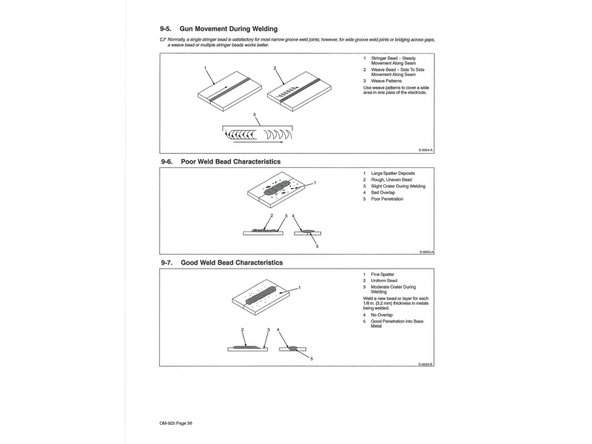
Normally, a single stringer bead is satisfactory for most narrow groove weld joints; however, for wide groove weld joints or bridging across gaps, a weave bead or multiple stringer beads works better.
-
-
-
Beginner’s Guide To MIG Welding. Everything you need to Get Started & More!
-
-
YouTube weldingtipsandtricks Mig Welding Basics Series 1- 4
-
-


5 Comments
This article offers great insights into welding techniques. I’ve been learning about stick welding recently, and it’s amazing how versatile this method is for various applications. For beginners looking to dive deeper, I found this <a href="Growelds">stick welding</a> guide really helpful!
Electroweld - Resolved on Release Reply
Thanks for this detailed guide on <a href="Growelds">MIG welder</a>. It’s amazing how far welding technology has come. I’ve been comparing different 180 amp MIG welders, and I find it hard to choose. Your recommendations would be appreciated!
Electroweld - Resolved on Release Reply
Great post! I’ve been in the market for a new <a href="Growelds">MIG welder</a>, and your insights really helped narrow down my choices. I recently came across the 180 amp models, and they seem perfect for both hobbyists and professionals. Would love to hear your thoughts on them!
Electroweld - Resolved on Release Reply
You have provided very helpful information in this Content. An extensive catalog of Welding Machines, most importantly, it is an essential element for your protection when working.
Jonathan Ryan - Resolved on Release Reply
Your information is very interesting. Thanks for posting. The benefits of ***Miller Welding Plant*** Machines are high technology and constant innovation.