
Parts
No parts specified.
-
-
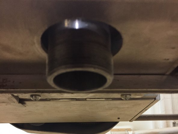
Jog the head to the front of the machine to access the router.
-
Arrow keys and Page Up/Page Down can be used to move the head.
-
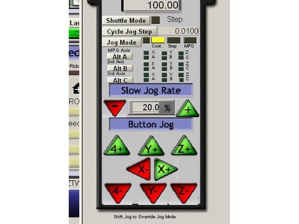
Press the TAB key to open the jog flyout to adjust the jog speed.
-
-
-
Engage the spindle lockout
-
Remove the key from the spindle lockout switch (wrenches are attached to the key)
-
Wait until the GREEN light is illuminated on the control stalk before approaching the spindle.
-
-
-
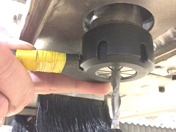
If performing a tool change, remove the existing bit, collet and collet nut from the spindle.
-
-
-
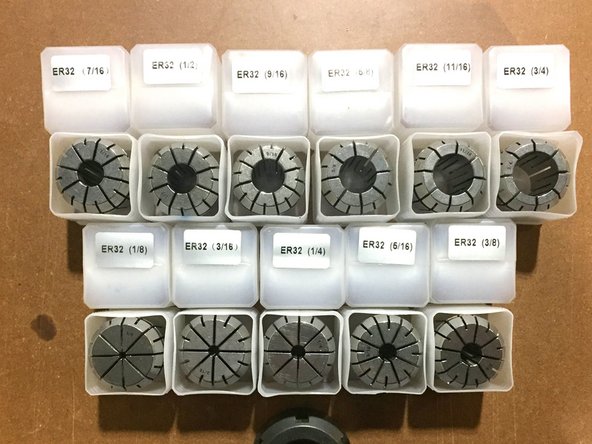
Each collet is marked with the size bit they are designed to hold.
-
Select the collet that matches the diameter of your tool bit.
-
Use only the collect that is marked with the size of your bit.
-
Metric bits should only be used in metric labeled collets, and vice-versa
-
Selecting an incorrect collect could cause the bit to move in the collet or be ejected from the machine!
-
-
-
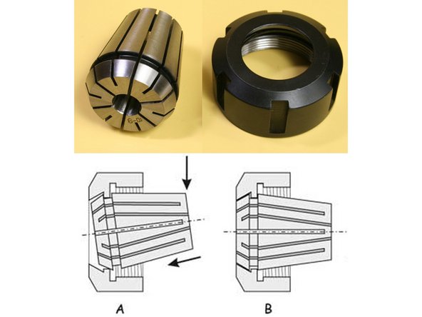
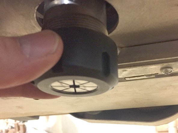
Install the collet into the nut by inserting it at an angle and pushing until the collet clicks into place.
-
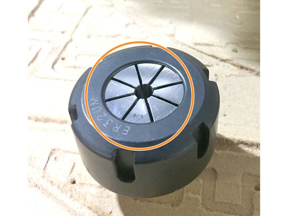
The collect is installed correctly when the collet is flush with the face of the collet nut.
-
-
-
Check the spindle taper and the outside of the collet to ensure they are free of any chips or debris.
-
Use a rag or your finger to wipe the taper and collet clean.
-
Chips left in the taper will cause the taper to be damaged or marred. This will lessen its ability to securely clamp tools.
-
-
-
Place the top spindle wrench onto the flats on the spindle to stop the spindle from rotating while you install the collet.
-
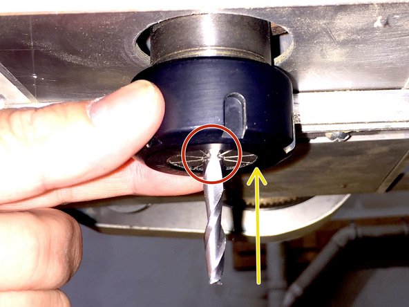
Install the collet on the spindle by starting the threads by hand.
-
Be very careful to not cross-thread the collet onto the spindle threads.
-
Once the collet threads have been started, insert the bit into the collet and tighten the collet by hand.
-
Ensure that the flutes of the bit are not inside the collet.
-
-
-
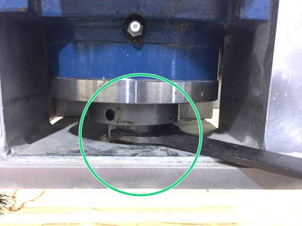
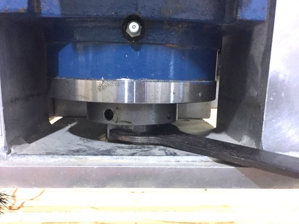
Insert the top wrench in the gap below the spindle mount.
-
Use the bottom wrench on the collet nut.
-
Tighten the collet.
-
Excessive force is not required, but do make sure to tighten the nut fully. Ask a checkout trainer to check your work.
-
-
-
Jog the machine to a good place to zero the tool height.
-
If zeroing to the bed, jog the machine over a clear area of the bed.
-
If zeroing to your workpiece, jog the machine over your workpiece.
-
Jog the head down to within about 1 inch of your zero surface.
-
Press the TAB key to open the jog flyout or use the ARROW and PAGE UP / PAGE DOWN keys to jog the machine.
-
-
-
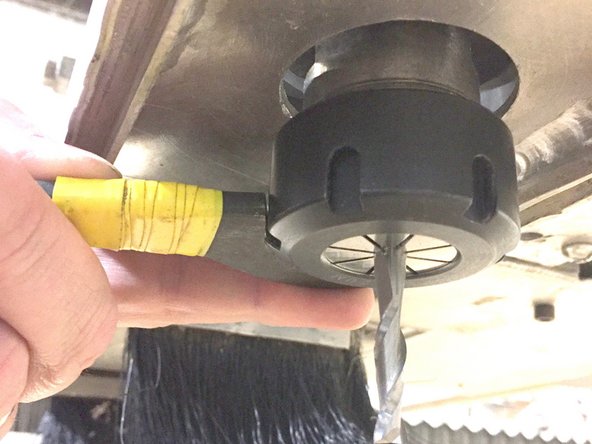
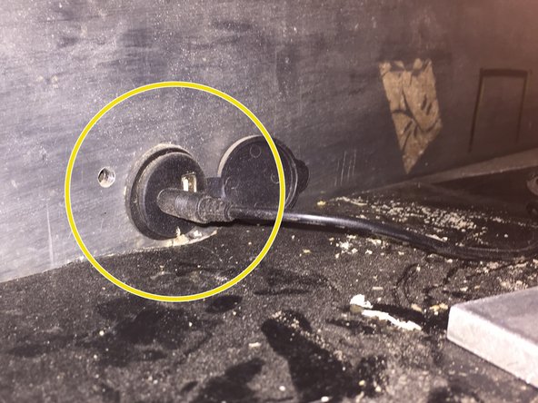
Ensure that the touch plate is plugged into its receptacle on the side of the machine
-
Place the touch plate under the bit.
-
Attach the magnet to the side of the collet nut.
-
-
-
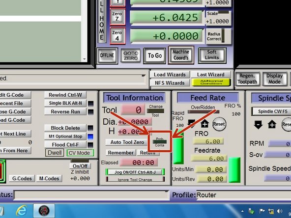
Lift the touchplate and touch it to the bit.
-
'PROBE CONTA" LED lights in the Tool Information panel should illuminate.
-
If the LED does not light, ensure that you have good contact with the magnet and that the plate is plugged into the machine.
-
If this LED does not light when touching the plate to the bit the machine will NOT be able to detect the contact and will drive the bit into the plate, potentially damaging it and/or the bit.
-
-
-
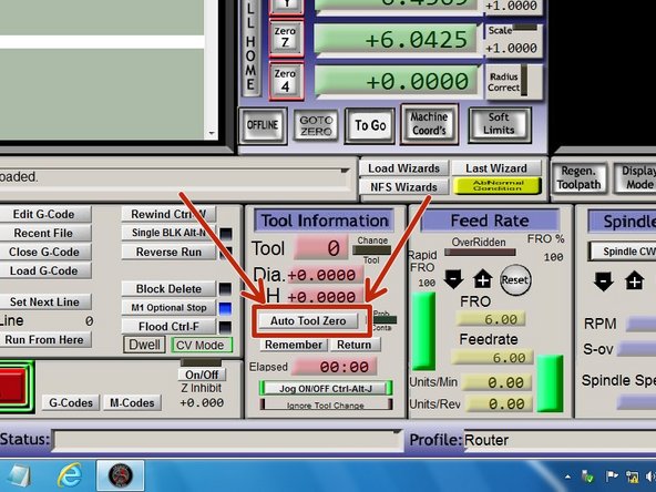
Click "Auto Tool Zero"
-
The machine will jog down until it contacts the touch plate and then sets the Z-zero accordingly.
-
Remove the touch plate from the machine and place it out of the way.
-
-
-
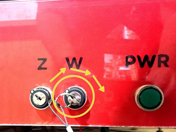
Insert the wrench key and turn to the "ARM" position.
-
The light stalk will illuminate YELLOW indicating that the spindle control is armed.
-
Stow the wrenches on the magnet on the side of the control box.
-


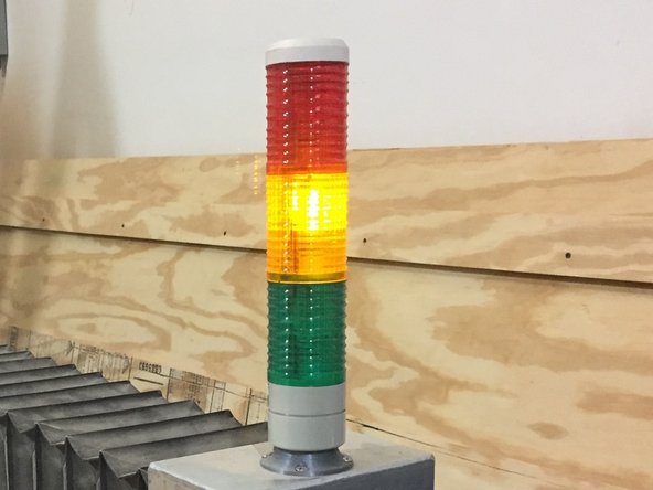
If performing a tool change, press "CYCLE START" to continue the job.
If this is your first tool installation for a job, proceed to the "Running a job SOP"
If performing a tool change, press "CYCLE START" to continue the job.
If this is your first tool installation for a job, proceed to the "Running a job SOP"
Cancel: I did not complete this guide.
One other person completed this guide.