Difficulty
Moderate
Steps
11
Time Required

User-Contributed Guide
This guide is not managed by the site's staff.
Introduction
This guide explains how to replace the actual cutting bit in a tool holder. This can be done when you need a specialty cutter which is not in the standard tool list, or to replace broken and damaged bits.
Measuring the length of the new tool is necessary to update the machine offset table so that all bits will cut at the same depth. This can also be performed if there is any concern that a bit has slipped or an existing offset is incorrect.
-
-
Use the guide "Pick Up a Different Tool Holder" to select the holder you want to replace or load a new bit in.
-
-
-
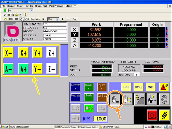
Make sure the controller is in "Continuous Jog Mode."
-
Jog the spindle to the front of the machine and high enough that you can easily access the tool holder collet.
-
Click the "Dust Shoe" button to raise the dust shoe out of the way.
-
-
-
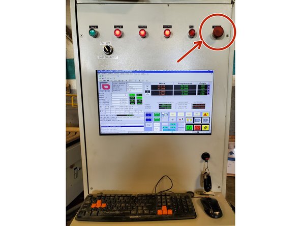
Press the E-Stop on the main control cabinet to disable the motors and spindle before proceeding
-
-
-
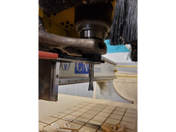
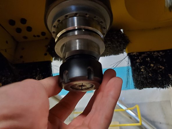
Use a wrench on the spindle flats and the collet wrench on the collet nut to loosen the nut.
-
Once the collet is loose, the cutting bit might slip out. Be careful not to drop it or cut yourself.
-
Remove the collet and cutting bit by hand.
-
-
-
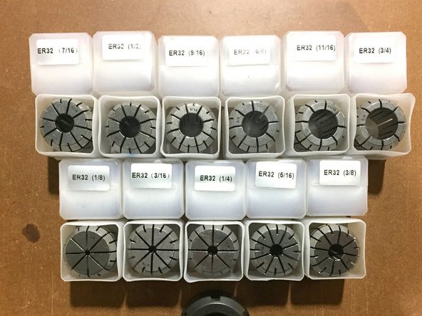
Each collet will be marked with its size.
-
Select the collet that matches the diameter of the shank on your cutting bit (not all bits have the same shank and cutting diameter).
-
Metric bits should only be used in metric labeled collets, and vice-versa
-
Selecting an incorrect collect could cause the bit to move in the collet or be ejected from the machine!
-
-
-
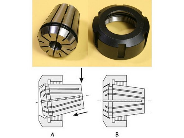
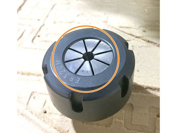
Install the collet into the nut by inserting it at an angle and pushing until the collet clicks into place.
-
The collect is installed correctly when the collet is flush with the face of the collet nut.
-
-
-
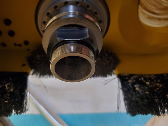
Make sure the inside of the tool holder taper and the collet itself are free from dust and chips. Clean as needed.
-
Start threading the collet and nut onto the tool holder by hand.
-
Be careful not to crossthread the nut. There should be very little resistance to turning at this point.
-
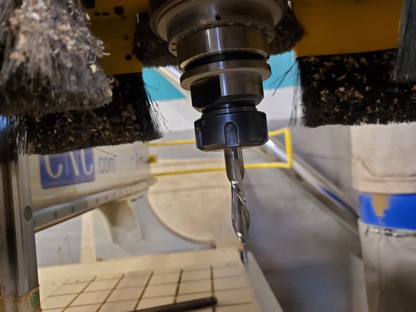
Insert the bit to the proper depth and tighten the nut by hand until the bit is held in place.
-
Place the flat wrench on the flats of the tool holder to prevent it from rotating.
-
Use the collet wrench to tighten the nut.
-
Excessive force is not required, but do make sure to tighten the nut fully.
-
-
-
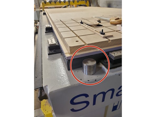
Clean off the round metal reference stud at the front of the machine bed.
-
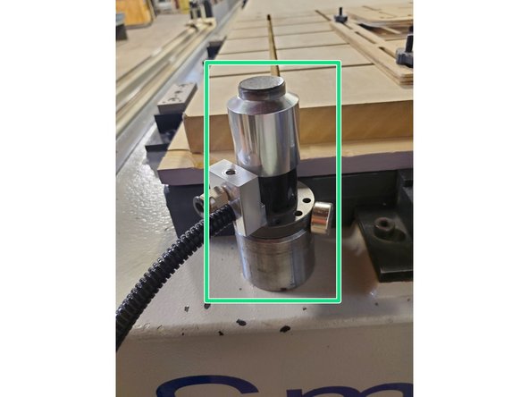
Place the tool length sensor on the stud. It should sit flat and be held by the magnets.
-
-
-
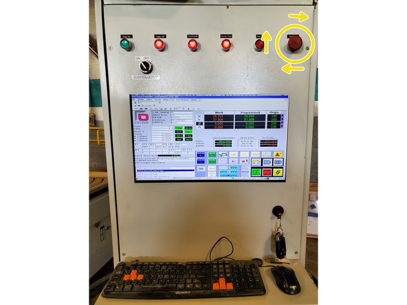
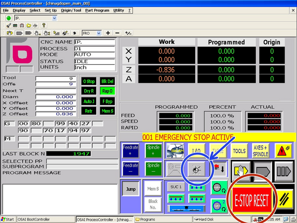
Release the controller E-Stop button by twisting clockwise.
-
Click "E-Stop" reset to clear the warning message.
-
-
-
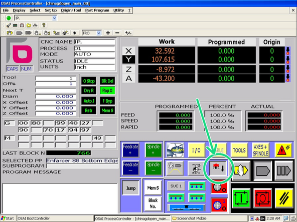
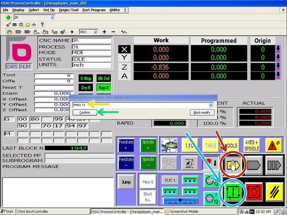
Click the "MDI" mode button to open the g-code entry window.
-
Type "M401 Txx" where xx is the currently loaded tool number.
-
Click "Confirm."
-
Click the "Cycle Start/Run" Button to execute the tool length probing cycle.
-
This will cause the machine to move over the sensor position and begin to lower the tool to the sensor.
-
-
-
Carefully monitor the probing sequence.
-
The bit should lower slowly until it barely depressed the sensor button and then raises back up and repeats multiple times.
-
If the spindle does not raise immediately after first contact with the sensor, press an E-Stop to prevent further damage to the machine.
-